BMRC tries to have one operating session per month except during the summer, when fewer operators are available and layout work is usually done. The last session of the 2022-2023 season was on May 20, 2023 and 14 operators ran 35 trains. Operators are now qualifying in the various jobs in a session, including train crews and yardmasters. As members learn new jobs, the sessions become more and more interesting and fun. Our new members rapidly learn the difference between operations and “running trains in circles.” As BMRC built its railroad and then rebuilt it in 2014-17, operation was kept in mind in its design.
Model railroad operation means different things to different people, but in general, it means to operate a model railroad in as prototypical a manner as possible, where each train has a destination and a purpose. A session on BMRC’s layout is planned to represent a day in the operation of the C&O and CRR railroads over the areas we model in the period of 1955-1965. With a very large layout like BMRC’s, there is a certain minimum manpower required to have a good operating session. We operate over 400 freight and passenger cars with up to 40 trains in a 3-4 hour session. Approximately 10 people would constitute a minimum for a session, assuming one-man crews. The club has operated with as many as 50 operators in the past, when operating with a visiting club. The layout requires a minimum of about 50 C&O and CRR locomotive units. After our initial sessions, setting up a session normally requires only about 2 people for two hours, depending on how the layout was left after the previous session.
On one occasion in 2019, we decided to have an all-steam session. We had every train in the session running with steam engines. We had over 30 engines provided by members on loan for a day. We had to give a little on our tradition of operating only C&O and Clinchfield engines and utilized a few from foreign lines. The roundhouse turntable at Huntington Yard was put to work frequently, as were the wyes at Ashland and Elkhorn City to keep the steam engines running forward. Passenger trains, freight trains, coal trains, and switch engines at the yards were all steam and quite a few were sound…………..resulting in bells and whistles not often heard on the BMRC layout. It really brought back memories to those of us who are old enough to remember when steam was everywhere.
On April 24, 2018 BMRC hosted a joint operating session with another club from Montpelier, OH. We had 8 visiting operators and 13 of our own and enjoyed several hours operating together. A total of 31 trains were run during the session, including passenger trains, mail trains, ore and coal unit trains, freight manifests, and local freights switching industries all over both the Clinchfield and C&O routes on the railroad. Both Huntington and Elkhorn yardmasters were kept busy and the Armco Steel mill near Ashland, KY was operating all though the session.
We began scheduling monthly operating sessions in September 2018. Thus far, sessions are being planned for Sunday afternoons only as this seems to be the day when most operators are available. Dates will vary, depending on other club activities. On January 26, 2019 we had a session with 11 operators and ran 34 trains in about 5 hours. Sessions are running more smoothly as everyone gains experience. With over 400 cars and 50 locomotive units operating for 4 to 5 hours, we have had very few problems with “bad order” cars and locomotives with bad performance, largely due to regular maintenance between sessions. The maintenance is done on weekdays by a few available retired members.
Prototypical operations require a traffic control system that represents those used on railroads of the 1950’s, such as automatic block signals (ABS) or centralized traffic control (CTC). The BMRC railroad employs a system with the option of a CTC system where the entire C&O and CRR sections of the railroad are controlled by a dispatcher or a system where signals operate as block signals and turnouts are operated manually. We now have about 150 detected blocks, 56 turnouts, and 224 signal heads that can all operate in either “operations” mode or “display” mode. We have the option of running trains on 6 independent loops (or several other similar options) for open house display mode. When in “display” mode all signals operate in ABS mode and turnouts are locally controlled.
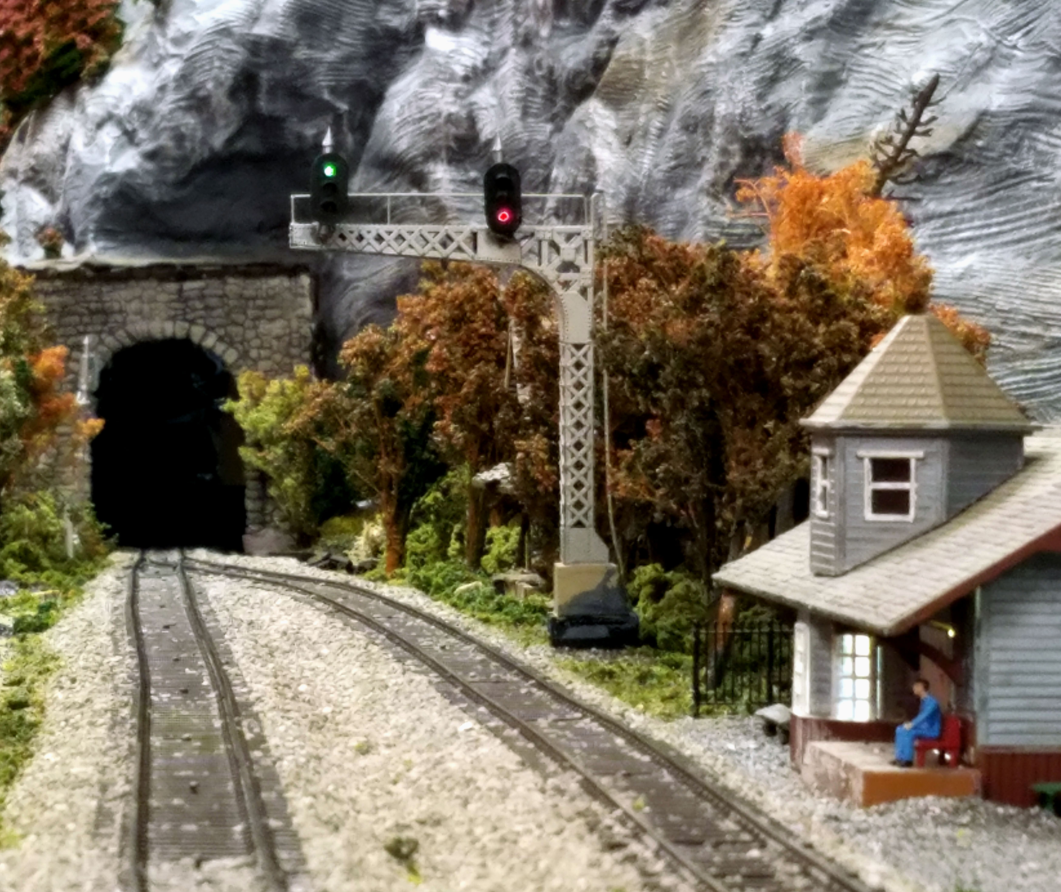
Typical signal bridge in ABS mode
The entire railroad is displayed on the dispatcher’s panel in the DS office. Turnouts, signals, local control, CTC/ABS mode, block occupancy, and allocated track are all shown in colors. Occupied blocks are shown in red in all modes. All other items are toggled by putting the cursor on the turnout, signal, etc. and left clicking on it. When in CTC mode, all signals remain red until the dispatcher allocates a section of track to a train. The dispatcher allocates track for a train by sequentially aligning turnouts and signals to green from the trains initial point to wherever the dispatcher decides to send it………….such as to a meeting point with another train. Whenever allocated, the blocks turn green with arrows in the direction of travel. As the train passes a block, the block turns back to white. Markers for each train running during operating sessions on our layout are located next to the respective railroads. These can be used by the dispatcher to identify trains in operation, particularly when multiple trains are operating at the same time. When the train reaches its destination, the marker is “docked” back to its normal storage position. All stations between Cincinnati and Charleston on the C&O, and between Elkhorn City and Johnson City on the CRR were given 3-letter codes for use with train orders and radio communication.
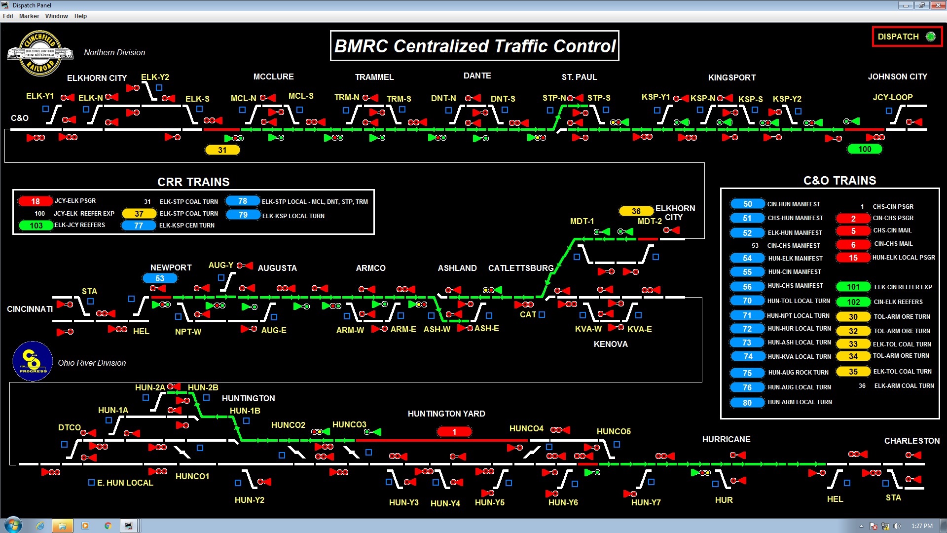
Dispatcher’s panel in CTC mode
When BMRC began its operating sessions in about 2003, we chose to start with a simple arrangement in which all members could participate and learn to follow train orders, make switching moves, operate under dispatcher control, etc. In an attempt to make our operating sessions more prototypical several years later, the club implemented a car card and waybill system. Initiation of this system was in conjunction with the completion of Huntington classification yard, a critical component in the use of waybills. The car card system is a popular way of operating and it is used on many model railroads. With this system, each freight car has a car card identifying its type, road name, car number, etc. and also contains a “pocket” for a waybill. The cards and waybills go with the cars and when the car reaches its destination, they go into the local waybill box. The introduction of waybills allows train orders and clearance cards to be used for their original purpose…………….traffic control. When operating a local freight train with a two-man crew, the engineer operates the locomotive and communicates with the dispatcher when necessary. The conductor calls the switching moves and is responsible for inbound and outbound waybills.
Car Card and Waybill Operations
There are probably as many ways of simulating and tracking model railroad car traffic as there are model railroaders. No one system is perfect. Each has its own advantages and disadvantages when it comes to issues such as the amount of paper work required, the amount of between session setup required, and the ease with which things can be changed and adjusted. Some systems are completely dependent on computers and others have no need for them. The trick is to find a system that meets the specific needs of the operating session but minimizes the amount of setup and paper work. Realistically, model railroading is supposed to be a hobby, and the last thing we need is to make an operating system that is so much work that nobody wants to get involved in setting up operating sessions. So let’s look at several methods of operating to see what each one has to offer.
1. Car for Car Replacement – With car-for-car replacement you make up a random train in your yard and head down the track. At the first industry, you pull cars currently in place and replace them with similar cars from your consist. Cars pulled from industries go to the rear of the train; cars being delivered come from the front. Soon you will have used up the original cars and start re-spotting cars you picked up a few industries ago. The advantage of this system is that there is no paperwork and it is almost painfully simple. The obvious disadvantage is that it doesn’t add much realism.
2. Switch Lists – Switch lists are tabular reports listing all cars that are to be moved in a train and what there destinations are. Switch lists are usually computerized as writing them out manually can be very tedious. Some operators may find switch lists difficult to decipher. After each operating session, if you are generating your switch lists by computer, you have to survey the entire layout to make sure cars ended up where the computer thought they would. If not, you need to make corrections to the database before the next list. Overall, computerized lists are more work for the setup crew than other systems. And……..operators spend as much time deciphering switch lists as they do operating their trains.
3. Color-Coded Tacks – This method requires a small hole in the top of each car to hold a tack which is color and alphanumerically coded so the each destination has its own color and letter code. You need as many tack colors as you have trains to run. Every piece of rolling stock on the layout except locomotives, cabooses, and cars captive in unit or passenger trains, needs a tack. You also need perhaps as many more for resetting the layout after each session. Finally, you need a tack of the appropriate color at each industry/spot. That tack is placed so the engineer can see it when working the industry.
With this system, the yardmaster can easily sort the color-coded cars into trains. However, we also have to indicate the recipient industry. That is done by a single letter on each tack written with an indelible pen. Thus, the yardmaster can sort not only by train, but can block (group cars together) by industry. The operator then matches the letter code to the actual industry out on the road. The system is very easy to learn, but the colored tacks tend to detract from the realism of the model scene. The advantage of this system is that there is no paperwork, just match the colors and letters on the tack. Also between sessions you have to replace all the tacks on cars that have reached their destination with new tacks for new destinations. This is easy enough for exposed tracks, but not for covered staging yards. And as you are replacing tacks, how do you know which tack to use as a replacement and still keep the traffic flow balanced? During each operations setup, much thought has to go into putting the right number of tacks in the proper cars. So overall, this method favors the operators, but puts a significant burden on the setup crew.
4. Single Destination Waybills – This system utilizes car cards and waybills (mentioned earlier). In this case, each waybill has only one destination printed on it.
On the waybill, as a bare minimum, is the destination station and industry, but other information can be included such as car type, routing code, spotting info, etc. As soon as you marry a waybill with a car card you have set up a move for that car. If you do this with all the cars on the layout, each car will now have a purpose for movement.
As train crews move around the layout, the waybill/car card combo tells them exactly what needs to be done with the car. Cars are picked up and dropped off until the train reaches all the destinations shown on the waybills. Between operating sessions, waybills are replaced in car cards for cars that have reached their destinations. This gives the cars new destinations and the process starts all over again.
The advantage of this system is that like on-car tacks, mixing up traffic is as easy as inserting a new waybill. No holes are required in your cars. Functionally, this is just the same as the tack system, except that the paperwork replaces the tack. The major disadvantage of this system or any car card system is that now you need a place to keep the paperwork as the car card must always stay with the car. Thus boxes for the car card are required at all yards and stations on the layout, just like many prototypical railroads had “WAYBILLS” boxes on the side of every station.
Another disadvantage is that, like the tack system, after each session EVERY car that has reached its destination has to have its waybill changed out. Thus you have to make many decisions during the setup process and it can get difficult to get things right. Wouldn’t it be nice if we didn’t have to decide what new waybill needs to be put in each car after every session? Well, the next car forwarding method, Multi-destination waybills solves this problem.
5. Multi-destination Waybills – Many car movements can typically follow a basic pattern of: car is loaded at an industry, loaded car is taken to another industry which unloads the car, and the empty car travels back to the original industry and gets reloaded and the cycle continues. Since this cycle can repeat indefinitely, why not create our waybill paperwork with both movements indicated on the waybill in a way that only one movement is shown during a session. Then between sessions the 2nd movement is exposed and the car is then automatically ready for the next session. All the thinking and fumbling of finding the right waybills between sessions to get the car where it needs to go is eliminated. This thought process is moved onto the waybill as it is being made up. Just like the single waybill system, between sessions every car on the layout that has reached its destination needs a new destination indicated, but now all that is required to reroute the car is for someone to just flip the waybills around to show the next movement. No thinking involved as those decisions were made already when the person created the waybill. The easiest way to make this change is to have the delivery crew flip the waybill when they deposit the waybill in the destination box.
Setup is now easy and basically automatic. Only when you want to vary the mix a bit are waybills changed out. Even though a car is basically only shuttled back and forth between two destinations, it may take as many as four operation sessions to accomplish the cycle. For example:
- Session 1: The loaded car moves from Industry A to the yard.
- Session 2: The loaded car moves from the yard to Industry B.
- Session 3: The empty car moves from Industry B to the yard.
- Session 4: The empty car moves back to Industry A.
You will see later that for the BMRC waybill system, four destination waybills are being implemented so car routing can be as simple or complex as desired.
The BMRC Car Card & Waybill System
The BMRC waybill system was developed using a customized computerized database program. This allows for easy management of the waybill and car card inventory and allows us to print really nice looking paperwork.
Car Cards – The first part of the BMRC car card & waybill system is the “Car Card”. Every car on the railroad used in operations must have a car card. (Unit trains and cards for blocks of cars are covered later.) The golden rule for operations is that if a car moves so does its car card. No exceptions. This includes moving cars around in between sessions or to clear an area for work projects. If this one rule is followed, the system should work well. If this rule is broken… Well, it is not nice to say bad things about those who have met an untimely death before us.
The car card’s sole purpose is to be a carrier for the waybill. So to serve that function, the card has a pocket on bottom into which the waybill can be inserted. There is only one piece of information required on every car card and that is the reporting marks which should match the marks on the actual car.
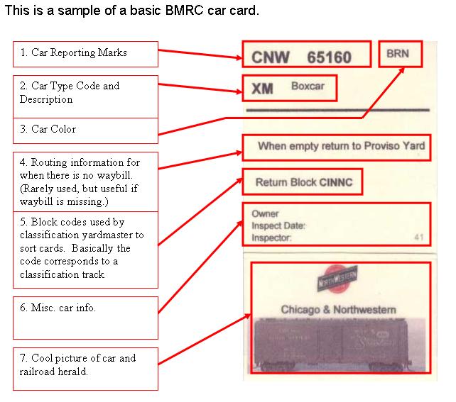
The BMRC waybill and car card program provides a means to print these car cards. In order to make things easier for the operators, the BMRC car cards have extra information to help in identifying cars:
- Car reporting marks – Required info that must match the car
- Car type code and description – should always match the car code on the waybill.
- Car Color – Helps to identify the car.
- Empty Return to Info – Provides the car with a default home destination if for some reason it has no waybill. This should be a rare event as all cars will generally always have a waybill.
- Empty Return Block Code – Provides the classification yard operator with a code which corresponds to the classification track on which the car will be sorted. These codes are discussed in detail in the waybill section of this document.
- Misc. Car info – Shows who owns the car and when it was last inspected. Also a small ID number is listed which should match the number on the ID sticker placed on the bottom of the car. This is basically a serial number and matches an ID code in the computer. This number is needed as we have many cars on the layout with duplicate numbers.
- Picture & Herald – The picture helps identify the car and the herald just jazzes the card up a bit.
Waybills – The second part of the BMRC waybill and car card system is the waybill. Basically a waybill’s sole purpose is to tell the operator where a car is going. When a waybill is matched with a car card and thus a car on the layout, it gives the car a destination and thus a purpose for moving in one of our trains.
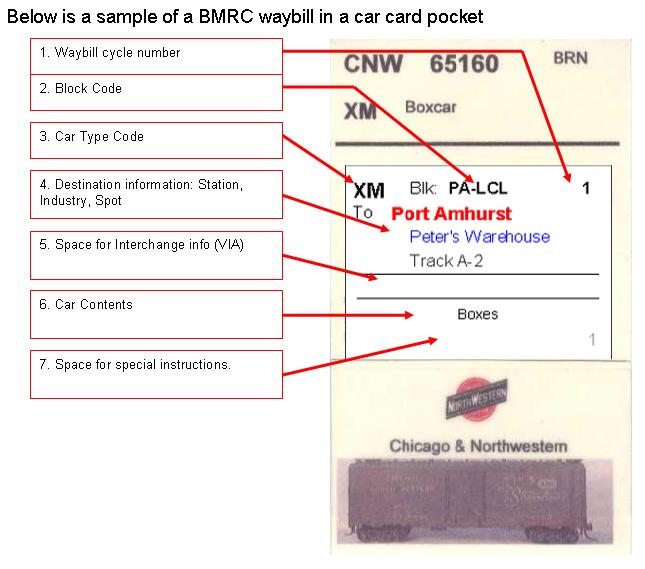
The BMRC waybill has the following information:
- Waybill cycle number – The BMRC waybill program generates a waybill that has 4 separate destination cycles only one of which is used and visible at one time. This number indicates which one is currently visible. This info is used by the setup crew and it is not used during operations.
- Block Code – Without some kind of coding system, the classification yard master would have to have a complete knowledge of every station on the line and which train it is served by. By putting this train code on each waybill, even someone who doesn’t know the railroad can classify cars because all they have to do is match the block code with a classification track. Even if you know the railroad, this code will speed things up in the classification yard.
- Car Type Code – This code should match the car card type code.
- Destination Info. – Every waybill will have the destination information listed in plain English.
- Interchange VIA information – When a car is destined for a location that is off the layout, the car has to be routed through one of our staging yards or interchanges. For off layout destinations, this space will list which interchange or staging yard the car is routed through.
- Car Content – This information is not needed for operations, but it enhances realism by giving the feeling that our trains are actually hauling something.
- Special Instructions – Use your imagination here. If there is anything special that has to be done to this car anytime during it travels to the destination listed, the instructions are place here.
As mentioned before, the BMRC waybills actually have four separate destinations listed on them. Only one of them is active at one time. The others are hidden from the operator by the virtue that they are written on the back side of the waybill or hidden by the pocket. Since only one destination is visible, there is no confusion for the operator.
Having multiple destinations on one waybill is where the power of this system lies. Between operating sessions, the members who are setting up the next operating session have to give all the cars that have reached the final destinations new routings. To do this all they have to do is go around the layout and turn over any waybill for any car that has reached its final destination. That’s it. No complex setup, not thinking. If a car is not at its final destination, the waybill simple doesn’t get turned and hopefully the car will reach it destination next session.
Waybills in Action – The BMRC waybill and car card system does not replace the train orders. The engineers still need to know where there trains originate, terminate, and where they are supposed to stop along the way. However, the waybills do replace the specific switching and consist instructions that we are currently showing on the train orders. So a complete set of instructions for a crew now consists of the train order document, and a pack of car cards and waybills. The train order tells where the train is supposed to go, and the waybills tell the crew what to do with each car in his train.
The following example illustrates the basic operation of the system. Imagine a local freight that originates in a classification yard, goes out on the line to perform pickups and drop-offs, and then returns to the classification yard. When the engineer arrives for duty, the yardmaster gives him his train order and a pack of car cards and waybills that correspond to the cars in the train. The engineer notes on the train order that he is a local freight turn and takes a quick look at the car cards to verify that he has the right train. The engineer performs the verification by minimally counting the cards to make sure it matches the number of cars in the train. Ideally the engineer will verify all reporting marks on the cars should match the car cards. If the yardmaster was worth his or her paycheck the pack of car cards will be in the same order as the cars are in the train, and the cars will be arranged or block according to the order of stations to be served.
If all checks out, the engineer checks the brakes and heads out. At the first station stop, the engineer does two things. First the engineer looks through the car cards that are located in boxes on the fascia to see if any cars in that town need picking up. The engineer knows a car need picking up if the destination on the card is not the location were the car is currently sitting. Secondly, the engineer looks through the car cards for cars in his or her train and determines if any cars need dropping off.
Once the pickups and drop-offs are figured out, the engineer then performs the work. Cars that are picked up are placed in the train, and the car cards corresponding to those cars are added to the train pack. Cars that are dropped off are spotted at the correct industry and the car cards for those cars are placed in the fascia boxes. That’s it, the work is complete and the engineer moves to the next station to repeat the procedure.
When the engineer returns to the classification yard, he or she parks the train on an arrival track and places the entire pack of car cards in the arrival tracks card box. The cars are now the yardmaster’s problem.
When the yardmaster has time to classify the arriving train, he or she will grab the car cards out of the arrival track box and begin sorting cars per the destinations and block codes on the exposed waybill. As cars are classified, their car cards are placed in each classification track’s box. Every track in the yard will have its own card box. Once classification of this train and other trains are complete, all the cars on one track basically represent a departure train and the cycle repeats.
Note that neither the engineer nor the yardmaster modified the waybill in any way. Waybills are only turned or replaced by the setup crew between sessions to reset the cars for the next session. This is another powerful feature of this system. Once the waybill system is setup, it is basically a self sustaining continuous cycle. Operation sessions would generally represent one day on the railroad, and the turning of waybills between sessions represent the time of loading and unloading of cars, and the next session picks up at the start of a new day.
The system is also self correcting. If anyone makes a mistake and spots the car at the wrong location, the next engineer to come along, most likely during the next operation session, will notice that the car is not at the proper destination and will move the card along.
Open top loads – Cars with open top loads always present a challenge with trying to simulate operations. You don’t want to see loaded coal cars routed to mine tipples and empty cars routed to consumer industries. Currently one of the setup functions is to swap out the loaded cars for empty cars between sessions. So what problems does that cause when waybills are added to the mix?
Ideally, our coal loads would be removable. So the when the setup crew is turning waybills, they would allow pull the coal loads from the cars at the steel mill for example and place the loads in the empty cars at the mines. However, most of our coal loads are plaster and swapping them out is not practical. Maybe if someone would develop a foam coal load, this would be achievable.
Since coal loads are not practically removable, that forces the cars themselves be swapped between sessions. So even though the cars are moving between sessions, the golden rule still applies, and if a car moves, so does its car card. The setup crew thus would take the car cards and waybills for all the cars being moved.
Technically then, the waybill in the car would not need to be turned, as the car is no longer at the final destination and during the next operation session the car repeats it movement from the mine to the users. But doing this would cause the same cars to always move to the seam destination every session. There is no harm doing this, but things can be mixed up a bit by providing multiple destination waybills for coal cars too. So sometimes the cars is destined for the steel mill, other times it would go to an interchange, and other times it may go to the power plant.
Multi-car Car Cards – Some of our coal movement are unit train based where all the cars move as a group to one destination. In this case, it seems excessive to have individual car cards for each car in the train. That is a lot of paperwork to carry when no sorting needs to be done. Therefore the BMRC waybill program allows for the creation of a car card that represents a block of cars that always move together as a group. The system currently is set up for use of one wayill for a unit train of 20 cars. Most coal unit trains of the BMRC originate on the Clinchfield and are interchanged to the C&O at Elkhorn City, KY. Some trains could be made up to go off the C&O at Charleston, WV or Cincinnati, OH, depending on the need for additional trains.
Layout Car Card Boxes – The car card and waybill system requires the used of fascia mounted boxes for holding car cards. Every location where cars will sit for any period of time will require boxes. This includes not only industries, but staging yards, interchanges, classification yard tracks, arrival/departure tracks, RIP tracks, etc. There are several ways that these boxes can be arranged, but there are advantages and disadvantages to each.
Let’s start with the simplest first: a staging yard. Imagine one of our staging yards completely filled with freight trains for operations and each train has 12-16 cars. Where do all those car cards go? Well to keep things straight, there really is no alternative to having one box for each track so that all the cars for each train are in one box by themselves. This makes it easy to pick up a train as you just grab the waybills in the box labeled with the track number your train is on. Okay then, one box per track for staging yards.
What about classification yards. Well again, nothing else makes sense except for one box for each classification track so that as the cars are sorted, the cards are dropped in the appropriate box. Arrival and departure tracks are treated the same as staging yard tracks since only one train can occupy an arrival track only one box is necessary.
Now when it comes to industries in towns, you have more options. Some layout owners like to have one single set of 3 or 4 boxes that are common for all the industries in one town. The set of boxes would be labeled with the town name and individual boxes themselves would be labeled Inbound, Outbound, Hold, and Off-spot. Cars arriving in the town would be dropped in the Inbound box. Cars to leave the down would be located in the Outbound box. Car that don’t move during a session are placed in the Hold box, and cars that arrive in town but can’t be spotted correctly due to congestion are placed in the Off-spot box.
While this method works well for small towns, it breaks down for large industrial areas. There would be so many cars in one box that sorting through them begins to become tedious. Furthermore, this Inbound/Outbound methodology is different from what makes sense for staging and classification track boxes. Therefore, BMRC implements a one box per industry track methodology (with some boxes serving multiple tracks where it makes sense) and that box is used for Inbound, Outbound, and Hold functions. This will require a bit more fascia space, but it has the advantage of keeping the cars sorted neatly. When an engineer is working a town, there should really be no confusion on what is between inbound and outbound cars. The hold function can be implemented either by turning the car card backwards in the box and establishing a rule that cars with reverse car cards are not to be moved, or a special “Hold Card” can be inserted in the waybill slot to instruct the engineer to not move the car this session. The Off-spot function can also be implemented with special instruction card.