From the outset, we decided to use JMRI freeware for monitoring and controlling signal and turnout hardware through a computer and, ultimately, to design our dispatcher panel and control system. So the input/output hardware that we have used over the years was all compatible with JMRI software. The finished railroad has 10 controlled sidings, 4 controlled double track crossovers, 4 double track termination points, and 10 controlled yard exits. This results in 58 turnouts (powered by Tortoise motors) and 228 signal heads. The main line and sidings involved with all these turnouts is divided into 144 detected blocks (for control only, not power). The input/output hardware used throughout the railroad is all connected to a CAT5 network (separate from the power loconet), ending at the dispatcher’s computer.
Hardware used for the system:
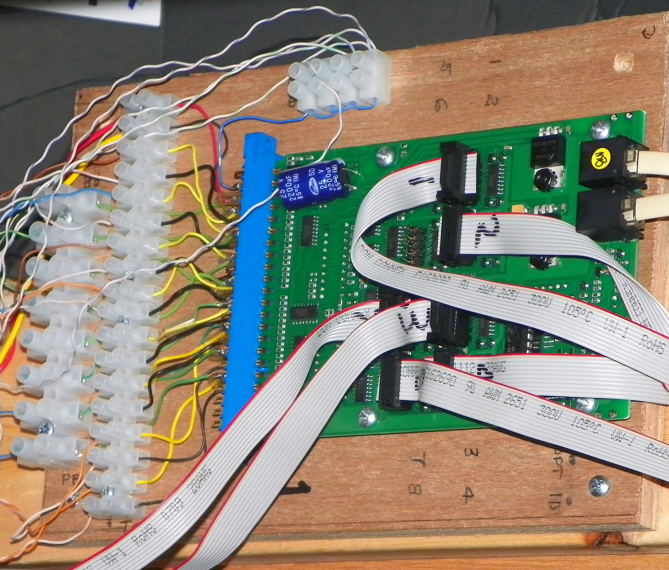
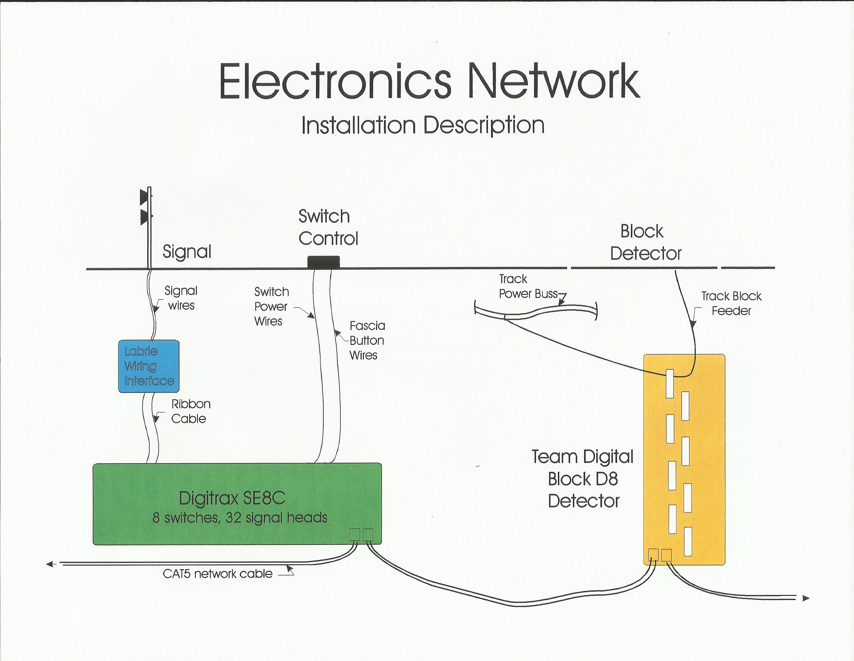
Turnout and signal control: 7 Digitrax SE8C signal decoders (each handles 8 turnouts and 32 signal heads)
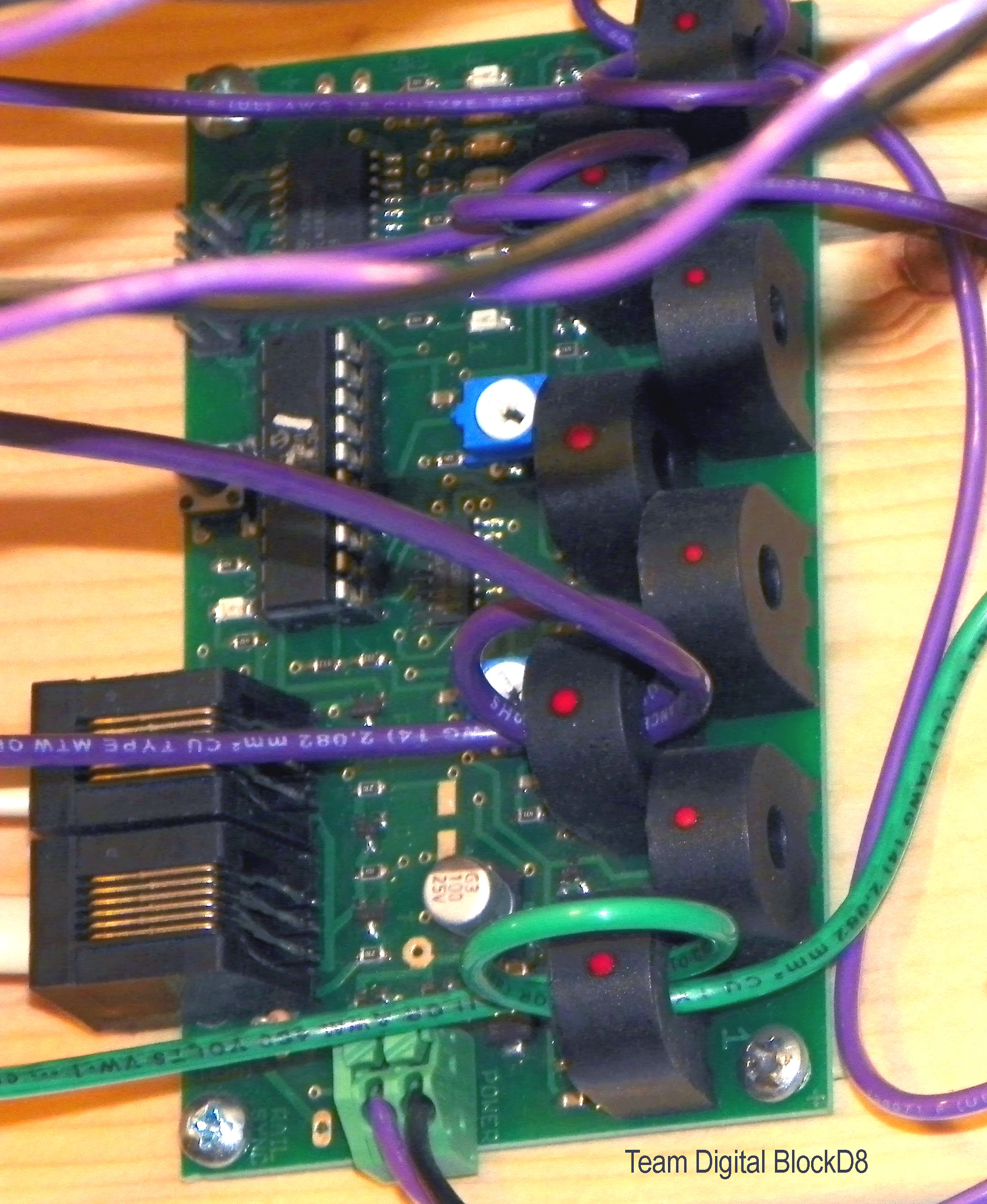
Block detection: 18 Team Digital BlockD8 block detectors
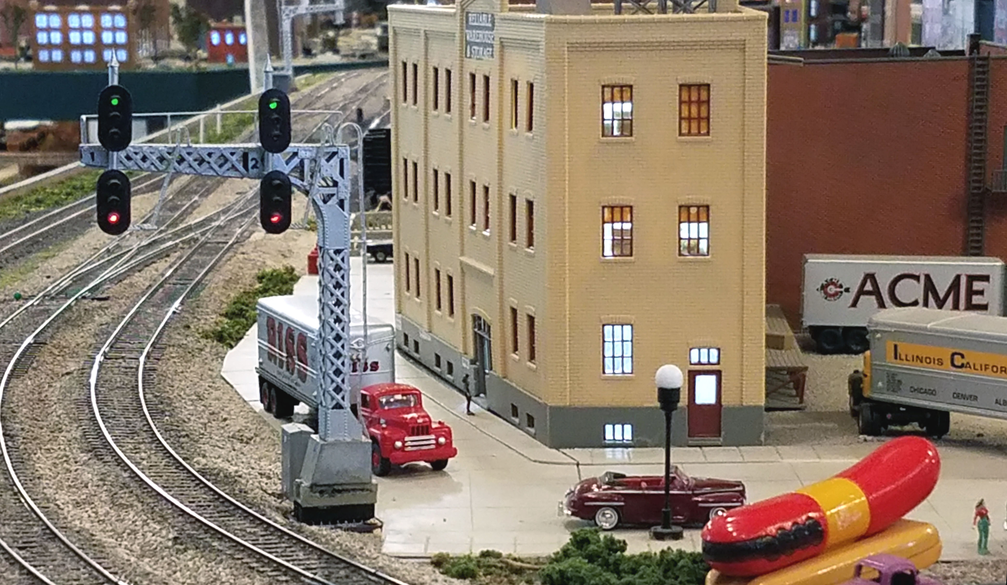
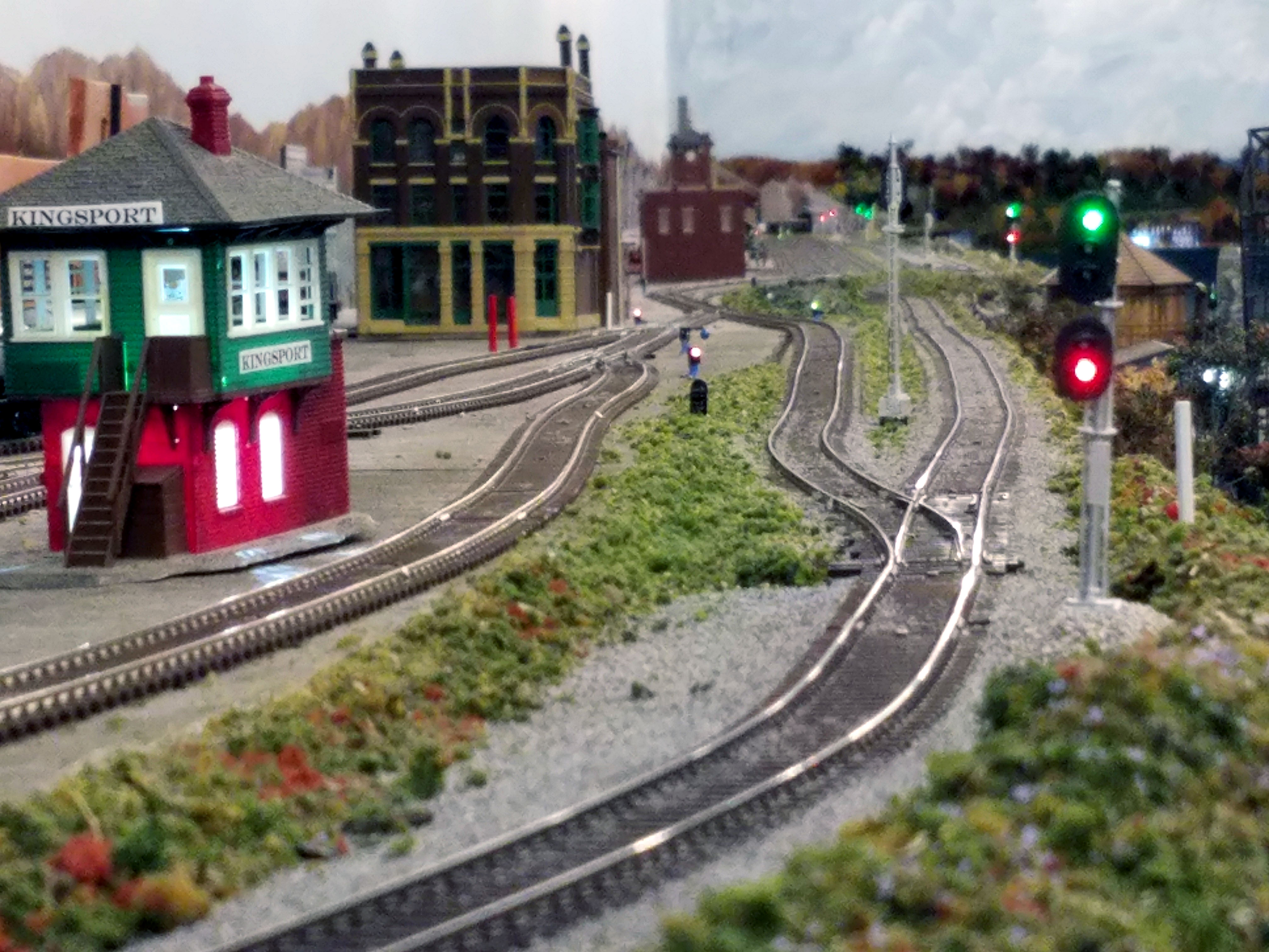
Signals: Oregon Rail signal bridges and masts (salvaged from our old railroad)
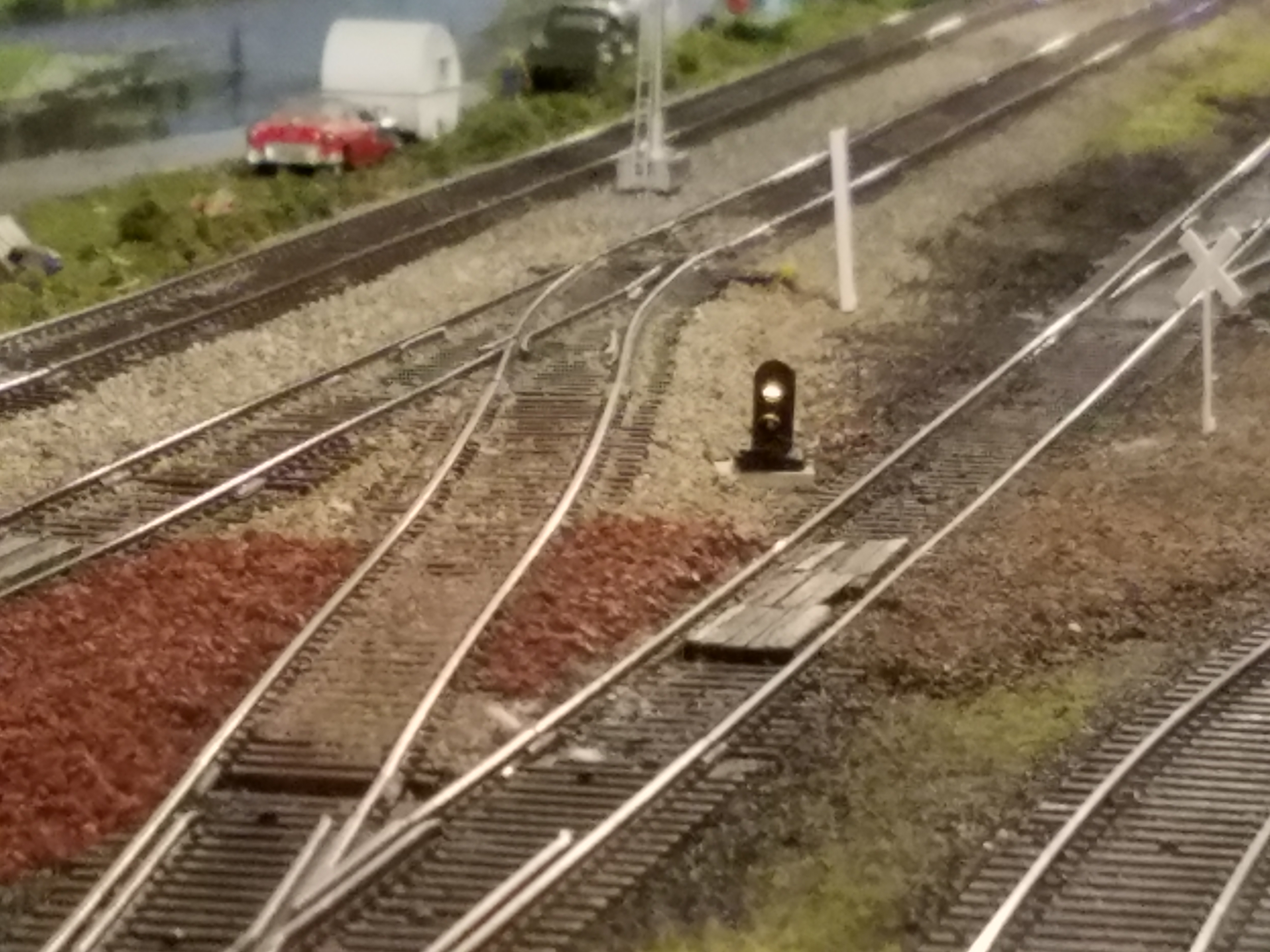
South Bend Signal HC-1, HC-2 single and double target block signals, and HCD 2-light dwarf signals.
12vdc power was provided with a Supernight LED driver. Power wire varied between 14 and 18 gauge stranded wire, depending on length. All turnout control from the SE8C’s was done with CAT5 cable wire (Appx. 24 ga) and each set of 4 signal heads at each end of a siding were connected to the SE8C with ribbon cable.
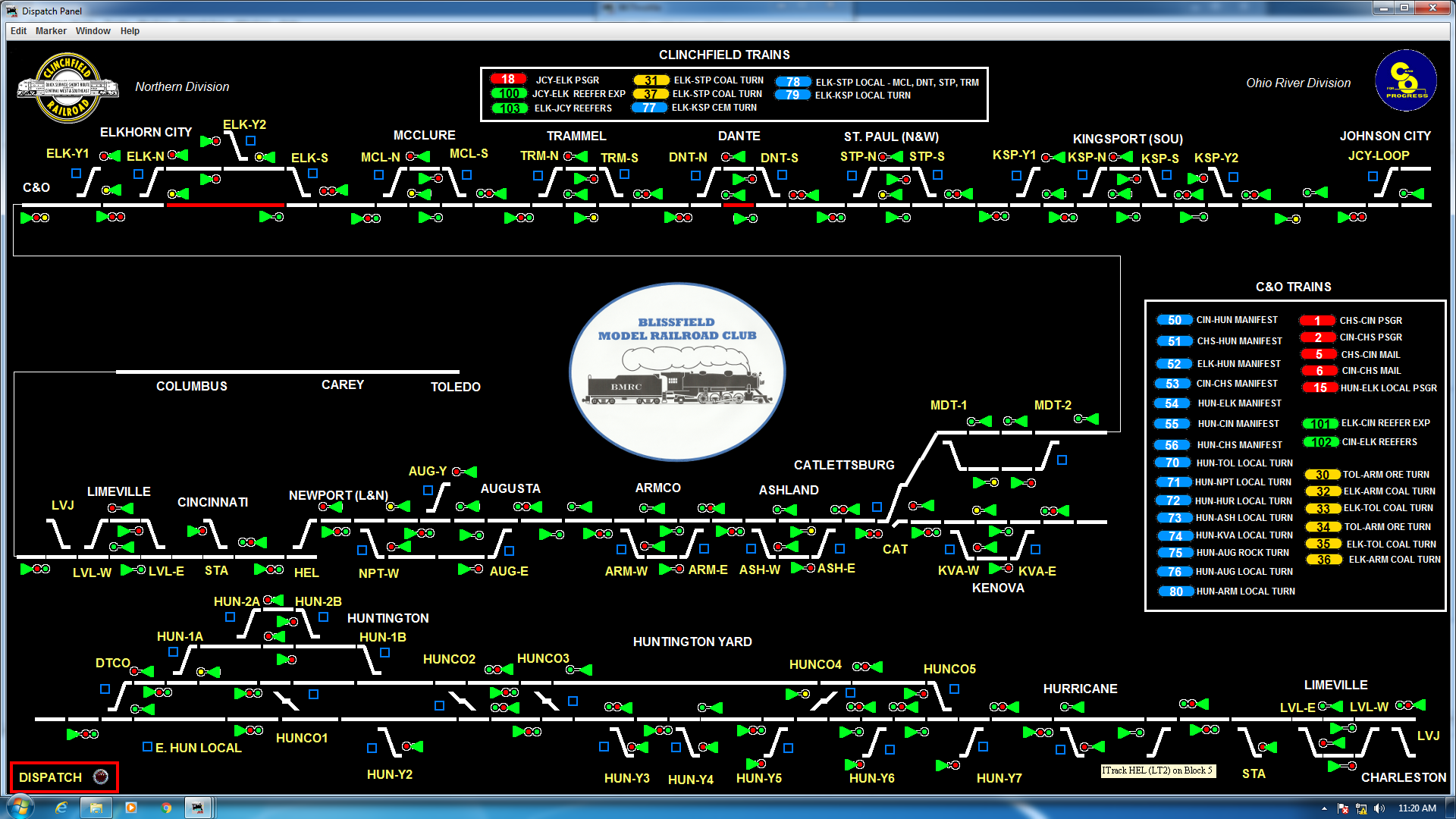
The computer used for the dispatch system is an old gamer-type computer (64 bit) using Windows 7. The JMRI Panel Pro freeware was used as a starting point and all the sensor identification, signal logic, etc. was brought to a fully operational status using the “Layout Panel” part of the system. The “Control Panel” software, which leads to a dispatcher’s control panel, was able to directly transfer all the data from the “Layout Panel” but considerable reprogramming had to be done to achieve the desired features we needed with our railroad. These included the ability to switch back and forth from dispatch to manual control as needed and to locally give local trains switching on and off the main line local control whenever possible. Switch and signal icons were customized and sized for the desired ability to operate them by clicking on the icon. We decided to use a 40-inch TV screen for a “modern” DS panel with good resolution, even though we try to roughly emulate a 1950’s CTC system operation.
Signal Decoder
Block Detectors
Installation Diagram
Typical Signals
Dispatcher’s Panel